restoration guide
Restoration labour is from £200. This fee is not based on an hourly rate but reflects attention to detail including mechanical work and lengthy testing to improve safely & reliability. This is not normally done in other workshops. Some amps need both repair and (some) restoration so labour can be between £80 - £200.
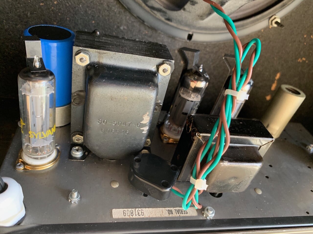
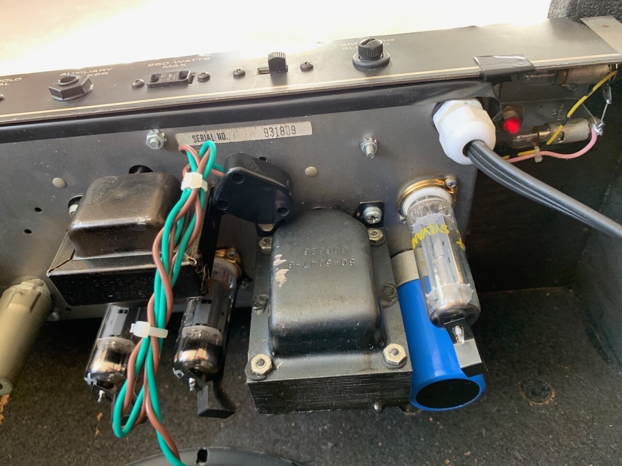
Before any electronic components are replaced a certain amount of mechanical work is necessary regarding high voltage terminals and the replacement of the power tube sockets.
A visual inspection under a magnifying glass is necessary to check for corrosion and material wear. Because of the high voltages electrical safety is paramount. A big part of a job is to remove solder from old deteriorated joints, grind and clean the terminals until clean metal can be seen; then resolder using new fresh solder and a little bit of solder paste and clean again. It is not good enough just to reheat a dry joint to repair it, the old solder must be removed first. Cracks, blisters or other structural problems must be investigated.
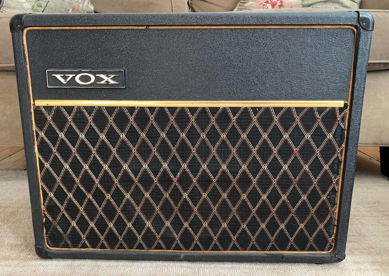
In older amps, (especially VOX AC30s) high voltage terminals suffer from horrendous structural problems. These terminals must be replaced using new high quality tag/turret boards. Sometimes new terminal boards must be constructed using materials such as Nylon 6/66 and individual tags.
In valve output stages the plate pin/terminal of a power pentode/tetrode such as the EL34/6L6/6550/KT88 is right next to one of the heater terminals (which are always connected to zero volts to avoid hum). Deterioration of the insulating properties occurs in both pcb material and tube socket due to condensation and thermal cycling. Arcing and burning can take place in this very small distance between plate and heater.
Internal arcing can cause a valve to fail regardless of external conditions such as dampness and high temperature. Quite often the reason is poor speaker connection when the primary output transformer inductance is the only component connected to the terminal and the magnetic field collapses. If the output becomes open circuited at such high voltages (approx 460v dc) while the amp is driven hard, even for a fraction of a second, then output tube failure is almost certain.
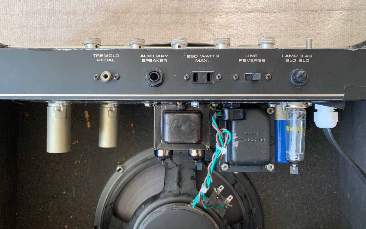
Arcing sometimes can also happen externally between the pins on the bakelite valve base and/or on the pcb/tube socket where it shows as a black carbon coating. Black carbon coating also appears sometimes on the glass of a tube, ie internal arcing and must be replaced. The AC current fed to a 4 ohm cabinet at 100w is 5 amp. If the speaker connection is not good it will reflect back to the primary of the output transformer as a load of a much higher value. Internal/external arcing will take place plus excessive screen current will result and this may cause screen to plate arcing and pentodes & tetrodes to fail. This is why badly worn output speaker sockets must be replaced, as well as the impedance selector switches, especially the old Marshall types.
In PCB Power Circuits : If the insulating properties of the PCB material have been deteriorated, a leakage current can be developed between the plate voltage and the control grid. This can cause intermittent reduction on the bias causing thermal runaway, ie red plates or “cherry-ing”. The remedy for the deterioration of the pcb material in output stages is to remove all the damaged area (due to burning for instance) and fill it with high-strength/high-temperature epoxy (sometimes mixed with colloidal silica). The solder has to be removed from the suspected dry joints (sometimes most of it) and one has to access how strong the adhesion of the copper track is onto the pcb. Then new solder has to be applied and where the adhesion is poor, the copper track must be removed, and the connections must be hard wired using copper wire of appropriate gauge. This is also the case in solid state power amps and power supplies because unlike valves (where the high voltage arcing usually causes damage) in transistors high current overheating due to output overload can damage PCBs very badly.
As far as the power tube sockets are concerned their insulation properties deteriorate with time and operation if they are made out of plastic/bakelite, so they must be replaced. Insulation doesn't fail in ceramic tube sockets and carbon deposits due to arcing can be cleaned. However, the metal part of the socket weakens and it doesn't hold the valves as well so its a good idea to replace them too. Fender valve sockets do not hold the valves well even if they are relatively new. In some amplifiers the diameters of the holes must be enlarged in order for the new better quality replacement sockets to be fitted and this can be a lengthy procedure.
In output transformers, condensation degrades the insulation between windings. Internal arcing can happen within the transformer creating carbon deposits leading to more leakage and intermittent failure of the output tubes. Sometimes it is impossible to trace this type of output transformer fault unless one dismantles the transformer itself! I first test the transformer electrically at full power, and I also test it for leakage and safely. If it passes the test it can be removed, cleaned and then apply slow setting epoxy (potting compound) between the windings to improve the insulation.
For similar reasons electrical components such as fuse holders, switches (mains and standby) etc must be replaced. Would you have 50 year old used plastic electrical fittings in your home? These amps become hot, work on very high voltages, in today's electronic world no other equipment works under these conditions. The position of certain components may have to be changed, away from components that are heat sensitive. Some resistors are replaced for ones with a higher power rating. I check the condition of high voltage electrolytic capacitors, and may change some of them if they have blisters. I prefer using high ripple, high temperature switch mode power supply types when I replace capacitors in the high power section of a class A amp such as the Vox AC30. Switches and sockets are checked and the whole amplifier has to be cleaned with special electrochemical's. Some potentiometers and signal sockets and switches may need replacing too.
In restoration jobs the output stage including the biasing circuit must be rebuilt. Sometimes a new and better biasing circuit needs to be designed and built to improve reliability.
A general problem with fixed-bias circuits in tube amps is the value of the grid resistor. For instance, RCA and most tube manufacturers recommend a maximum of 100k for the 6L6 tube. High grid resistance value could make the grid become less negative at operating temperatures due to leakage grid and gas currents. A less negative grid voltage results in more plate current, temperature rise and more gas and grid emission current, therefore a knock-on effect that causes tube thermal runaway.
The characteristics of various components drift with time and use so they need replacing. The output valves are replaced, its fired up to see how it performs. A series of bench tests using a dummy load, overdrive and so on, are done to check how each valve performs after the amp has been correctly biased. If the maximum ratings of a tube given by the manufacturer are exceeded tubes fail on a statistical basis, unlike semiconductors which fail on an absolutely certain basis. NOTE : This is why some amplifiers which exceed those maximum ratings may work with certain valves for years and then one puts in a brand new good set and biases the amp properly but then after a while you end up with one or two blown ones. This is a common design fault on modern valve amps and a problem when it comes to repairing them!
A sound test is done which leads us on to the small valves, and of course when the amp starts being used, other little problems may be discovered ... noisy operation, low gain and may also have to do repairs on circuits like vibrato, reverb etc might be necessary too. Finally the earthing and electrical insulations has to be thoroughly checked.


